Space Ranger5.1, printed on 04/02/2025
The Space Ranger pipeline uses automatic image detection algorithms to calculate the location of the fiducial markers, and find the boundaries of the tissue. 10x Genomics tested the algorithms on a wide variety of H&E images, tissues and samples, and found the detection algorithms to be robust. However, for immunofluorescent images, or in cases where the fiducial markers are obscured or tissue boundaries are unclear, manual fiducial alignment and tissue outlining will be required.
Loupe Browser 4.0 and later provide the Visium Manual Alignment Wizard for immunofluorescent images and other cases where more manual intervention is required. The wizard makes it possible to interactively align an image to a slide’s Fiducial Marker locations, perform fine-grained tissue selection with a suite of tools, and export the manual alignment into a Space Ranger run. This tutorial walks through this process step-by-step.
Loupe Browser 5.1 and later includes the option to load an additional overexposed capture to facilitate fiducial selection for immunofluorescent images. This overexposed capture can be included as an additional channel in the same image file, or as a separate image file, depending on imaging system capabilities. This capture is excluded from downstream analysis in Space Ranger and Loupe Browser.
The tutorial below demonstrates the alignment steps for a single-channel brightfield image, and a multi-channel immunofluorescent image for steps that differ.
The Visium Manual Alignment Wizard can be found on the Loupe Browser start page, at the bottom of the main panel.
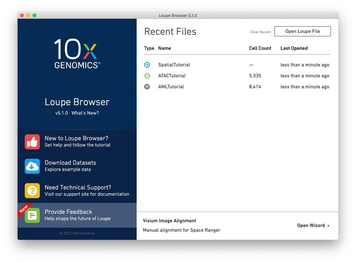
Clicking on the link starts the wizard. The wizard’s first page shows a schematic of Visium slides, including the location of the serial number on the slides, and the location of each capture area on the slides.
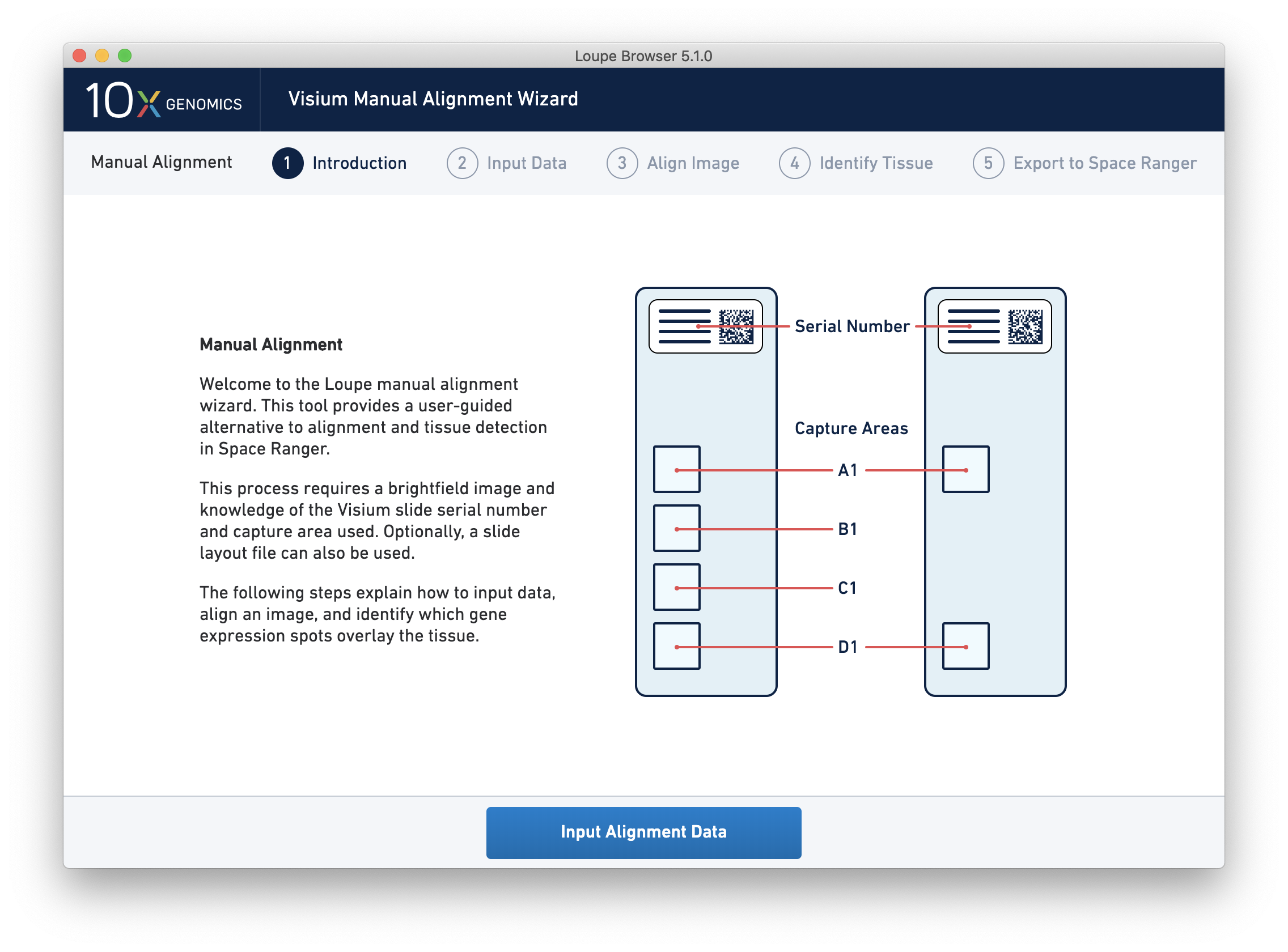
Since spot locations can vary subtly between different slides and different capture areas, providing the correct slide and capture area information for the image ensures the most accurate alignment and spot locations possible.
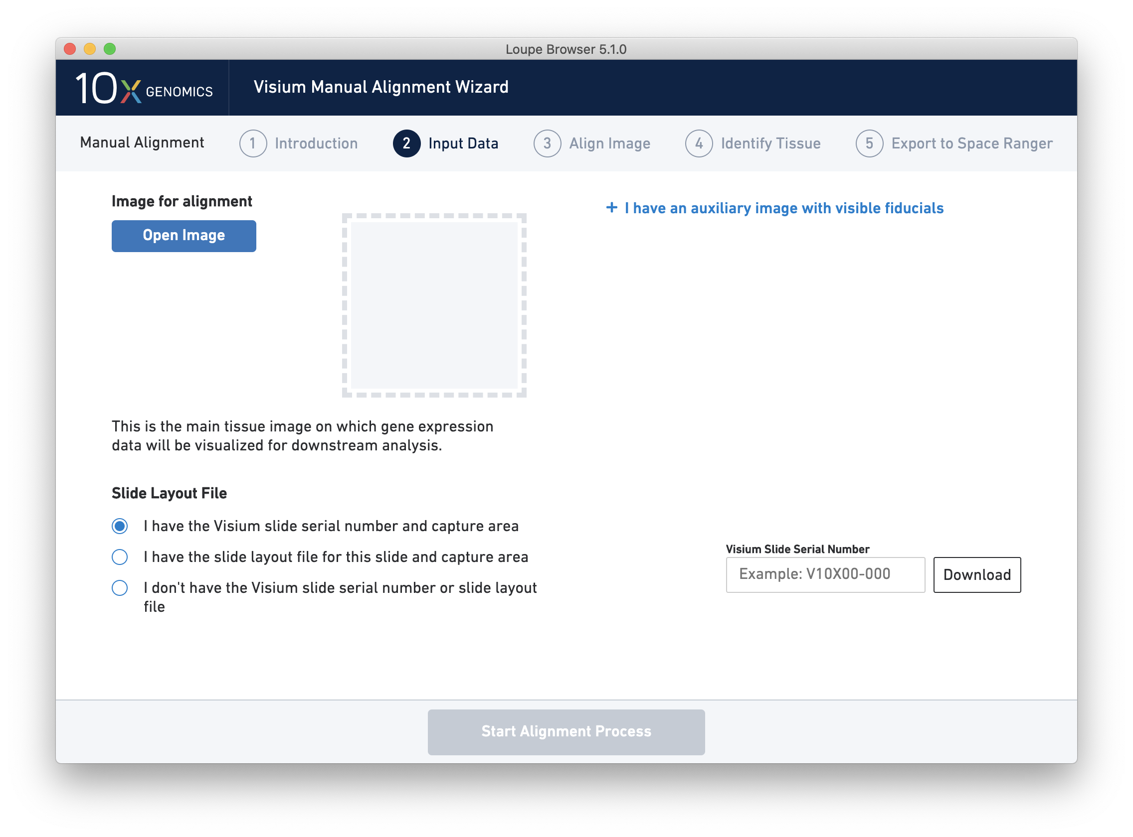
Next, click on Input Alignment Data to bring up the Input Data page, which contains prompts to load the image(s), and enter slide and capture area information.
The rest of the tutorial assumes the following resources for the H&E-stained image. While a practice immunofluorescent image is not provided here, the steps may be followed using the same slide serial number and capture area with any image that meets the requirements below.
The Visium Manual Alignment Wizard accepts the same types of image files as Space Ranger including:
Clicking on Open Image opens a file dialog that filters the current filesystem for compatible image files. Selecting a file triggers a brief loading process. If the computer running the wizard has insufficient RAM to efficiently load the image, the wizard requires confirmation to continue. This is only likely to happen for very large BigTIFF images.
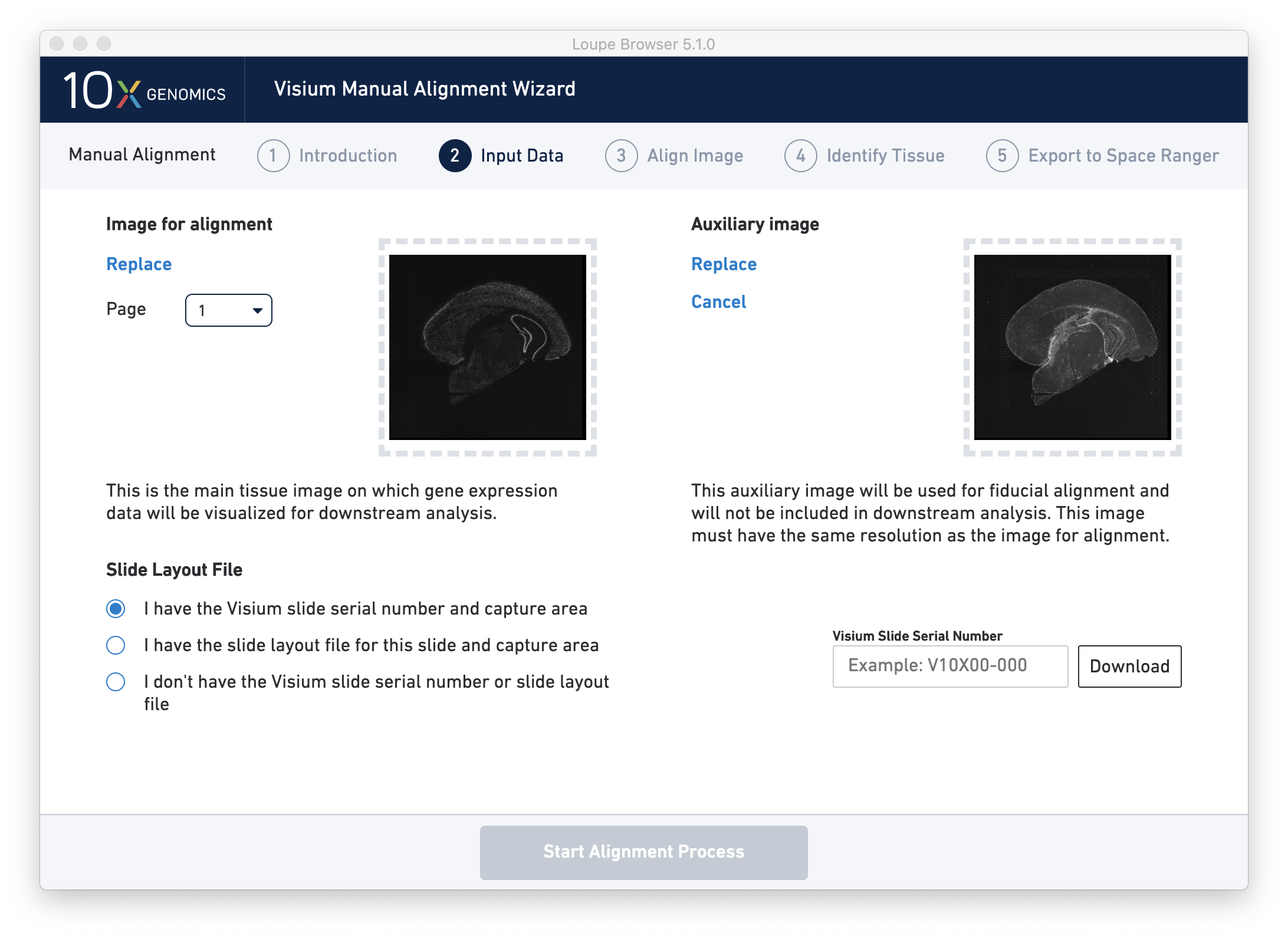
Once the image(s) are loaded, preview image(s) appear, as shown below.
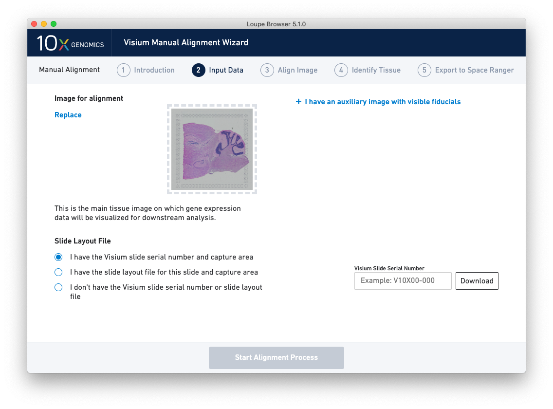
For multi-channel immunofluorescent images, the fiducial markers and/or tissue may only be visible in a single channel. Throughout the wizard, use the page dropdown to change the active channel selection.
If an additional auxiliary overexposed image is being used for fiducial alignment, click on I have an auxiliary image with visible fiducials and follow the same open dialog steps.
There are three options for entering slide information.
The Align Image wizard step uses the spot location information from the image and the spot offset file loaded in the previous step to enable interactive manual alignment, using the Fiducial Markers as a visual guide. The spots are aligned with the image, first in a coarse-grained manner through identification of the centers of the Fiducial Markers then in a fine-grained manner by dragging to make small adjustments.
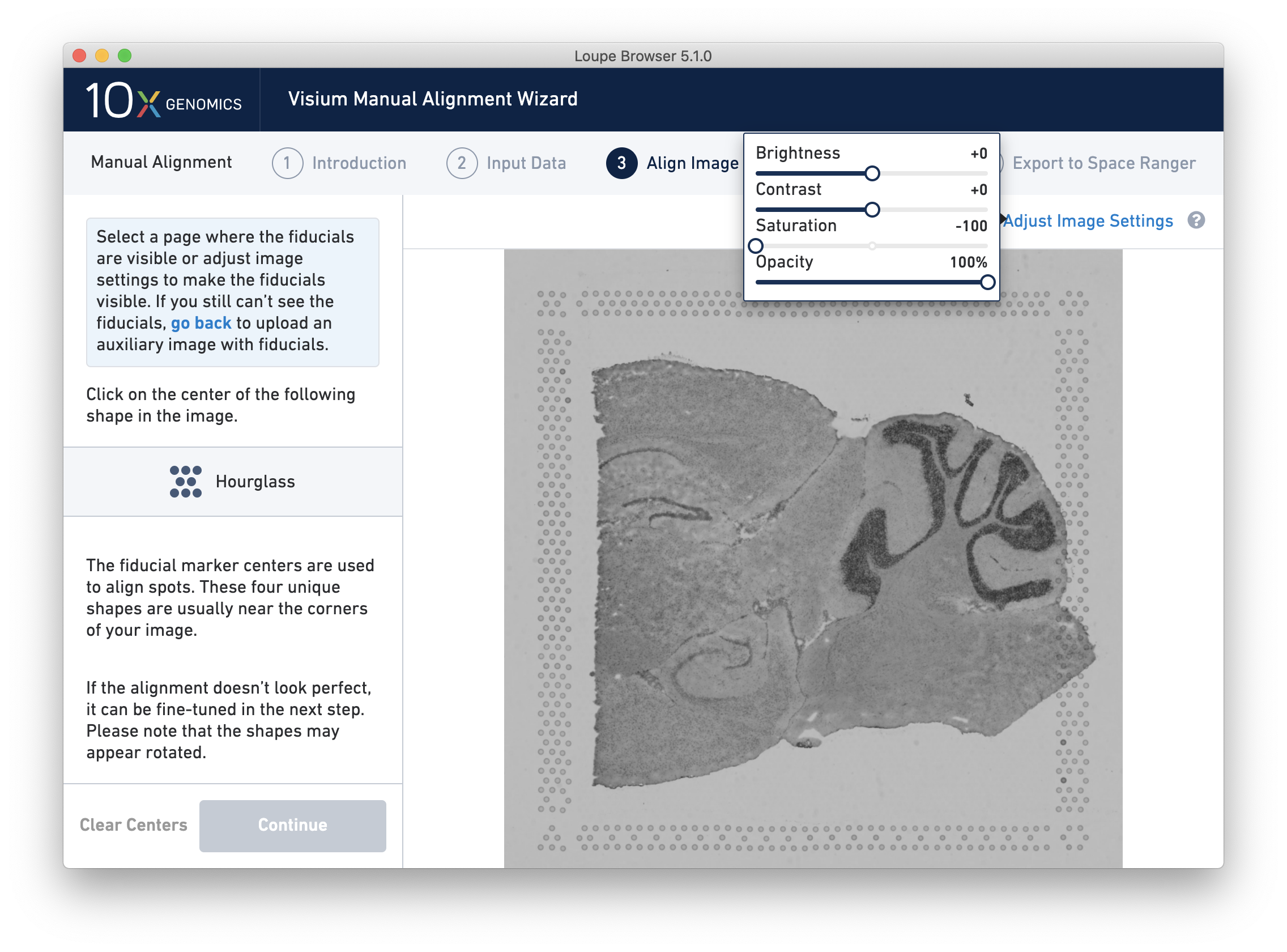
If the fiducial markers or tissue boundaries are dim, it is possible to adjust the appearance of the image while manually aligning by clicking on Adjust Image Settings link above the image. It is possible to adjust the brightness, contrast, saturation, and opacity of the grayscale image, which may make it easier to identify fiducial markers or tissue boundaries.
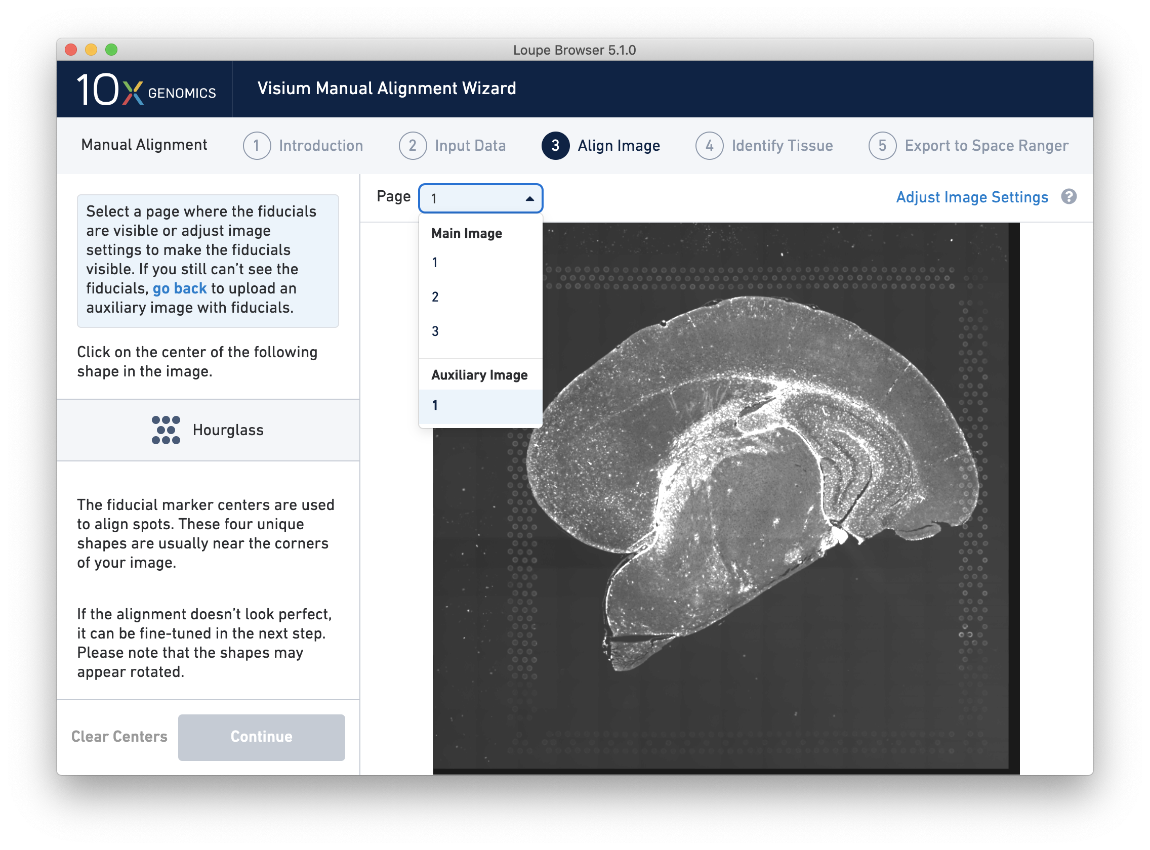
For multi-channel immunofluorescent images or when using an auxiliary image, it is important to begin by selecting a channel where fiducials are most clearly visible. Use the Page dropdown to select the correct channel. This may be an overexposed channel in the same file that you plan to discard downstream in your analysis.
If an auxiliary overexposed image was loaded in the previous step, it will be accessible as an additional option in the Page dropdown at the Align Image step for fiducial selection. This image must have the same resolution as the first image loaded for alignment.
Alignment instructions are located on the left side of the page, and the alignment tool is on the right. It is important to follow the instructions carefully, as prompts change subtly at each step and it is critical to map each unique shape correctly. See the four unique shapes below:
| Fiducial Markers | Shape |
|---|---|
 |
Hourglass |
 |
Filled Hexagon |
 |
Open Hexagon |
 |
Triangle |
If one of the corner shapes is obscured by tissue, do a best guess. Fine-grained alignment with three corners should still yield satisfactory results.
If one corner X is not centered, proceed with the remaining corners first, then click Clear Centers to reset.
After selecting and fine-tuning, a red Fiducial Frame is overlaid on top of the image, and the Fiducial Markers should be in alignment, as shown below. You may do additional fine-tuning at this step to ensure full alignment of the frame.
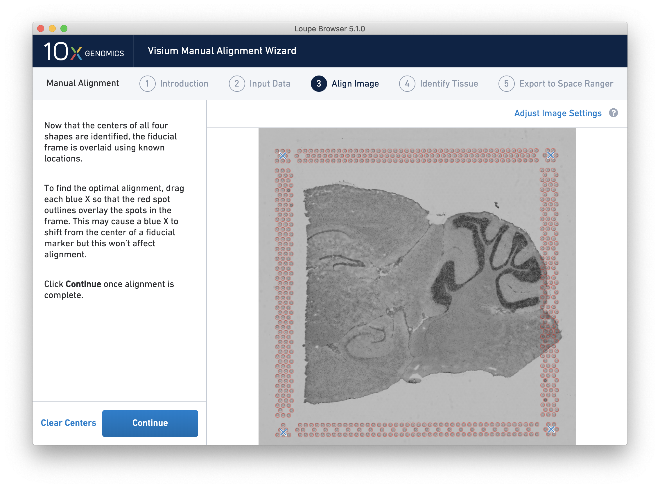
Clicking Continue to move to the next step, Identify Tissue.
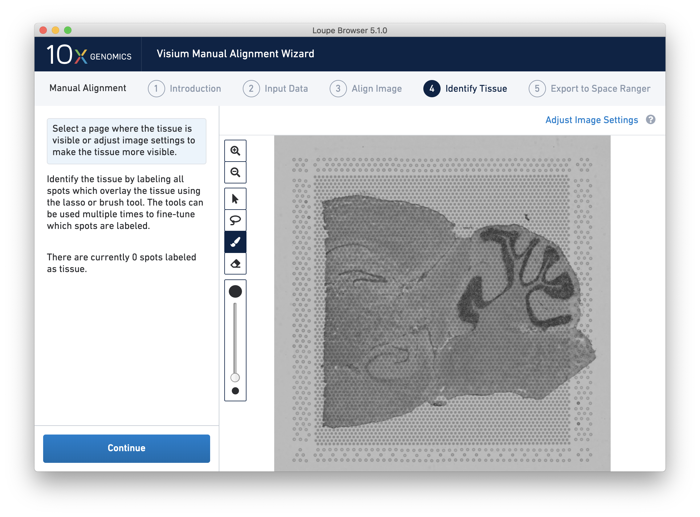
Accurate tissue boundary selection yields higher-quality data, lessens the likelihood of background-driven clusters, and provides accurate spot counts for fine-tuning sequencing parameters. When starting on the Identify Tissue page, the barcoded spots, with location inferred from the previous alignment step, are drawn on top of the image, as shown below.
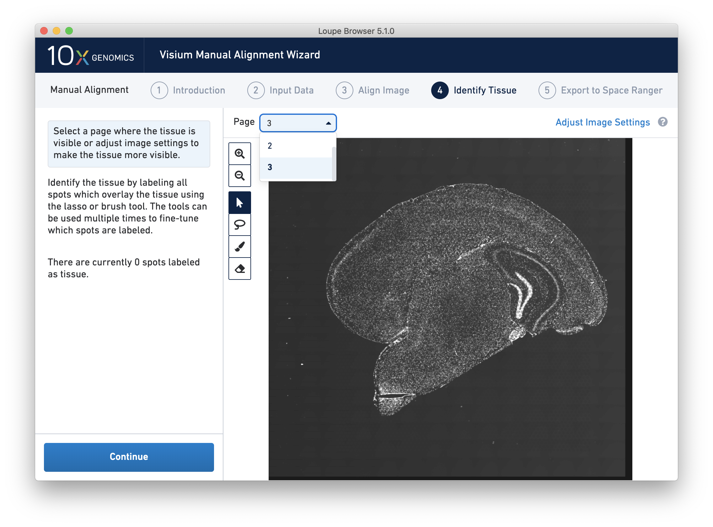
For multi-channel fluorescent images, the channel that contains the clearest tissue boundaries may be different from the channel that most clearly shows the fiducial markers. The active channel can be changed by clicking on the Page dropdown under the tissue alignment instructions.
A toolbar to the left of the image provides a variety of tools to perform both coarse-grained and fine-grained tissue selection. The tools are described in the table below.
| Tool | Description |
|---|---|
 |
Zoom in |
 |
Zoom out |
 |
Pan image - move right and left, or up and down |
 |
Lasso |
 |
Label as tissue brush (size adjustable) |
 |
Label as background eraser (size adjustable) |
 |
Size adjuster for tissue brush and background eraser |
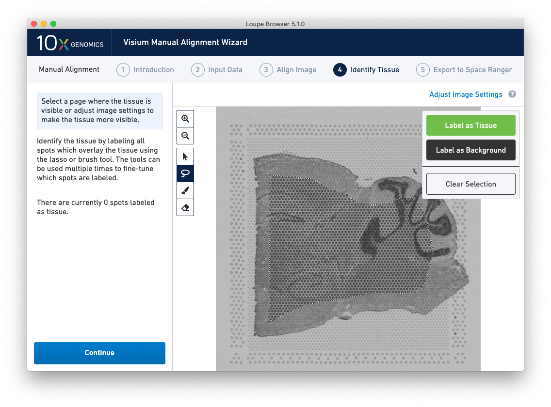
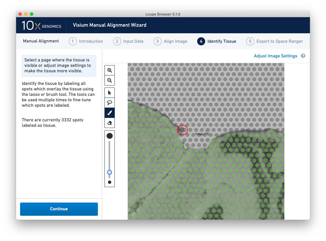
A typical tissue selection workflow starts with the lasso tool. By dragging the lasso around the tissue, it is possible to broadly select the area corresponding to the tissue. Currently selected spots appear to be darker than unselected spots, as shown below. When the drag is complete, a prompt appears. The selected spots can be Label as Tissue, Label as Background, or select Clear Selection to cancel the drag.
The above selection roughly corresponds to the location of the tissue, so Label as Tissue is the appropriate choice. Spots labeled as tissue appear green, and spots labeled background remain gray, as shown below.
In this manner, the Lasso tool can be used to create large areas as tissue, large background areas, or holes in the tissue.
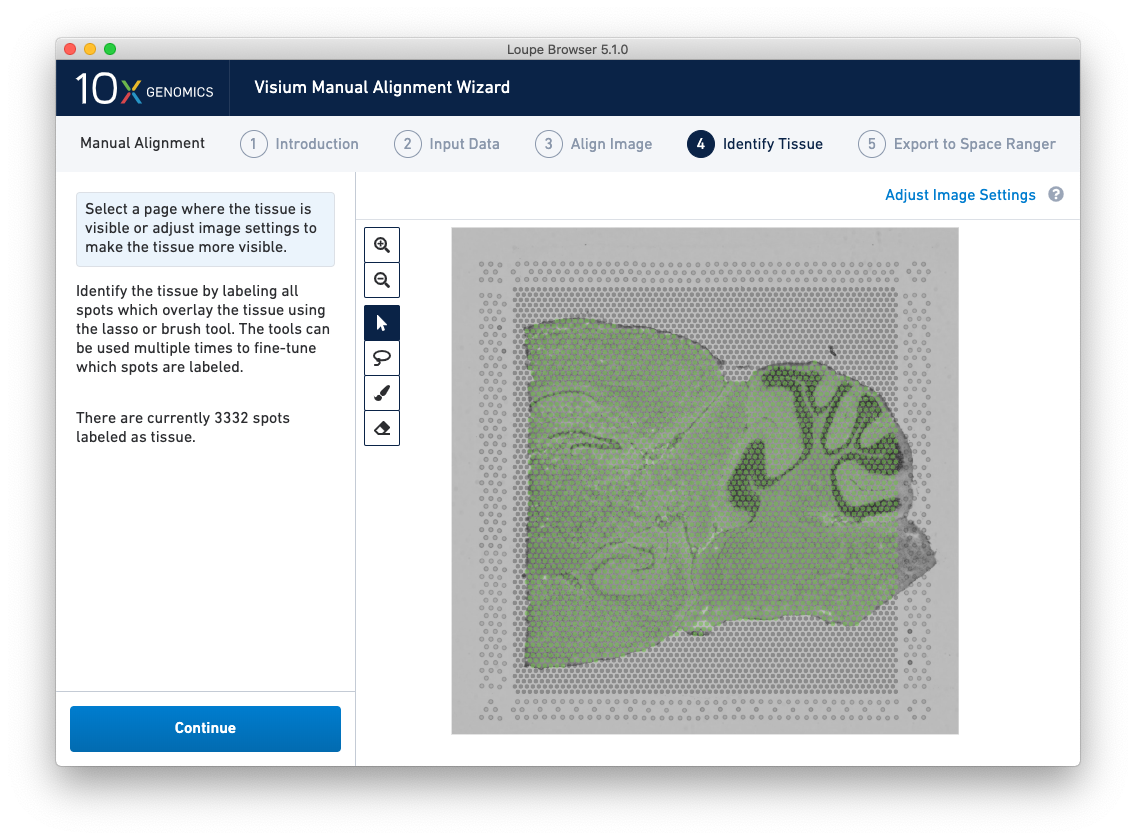
Because of the approximate nature of Lasso tool, there may still be spots labeled as tissue outside the tissue boundary. Use the Zoom tool and more precise label-as-background Eraser tool to refine the boundary. Zooming in two levels, and adjusting the eraser size to approximately two spots wide, provides a good level of control for refining the previous selection.
Both the label-as-tissue Brush and label-as-background Eraser have adjustable sizes, which can be configured through the slider beneath the toolbar. When complete, zooming out should yield a satisfactory tissue boundary.
Return to previous steps in the wizard to fine-tune, make adjustments, restart alignment, restart tissue detection, or enter different data. Once the alignment is satisfactory, the last step is to export the alignment file to Space Ranger. Click Continue from the Identify Tissue step.
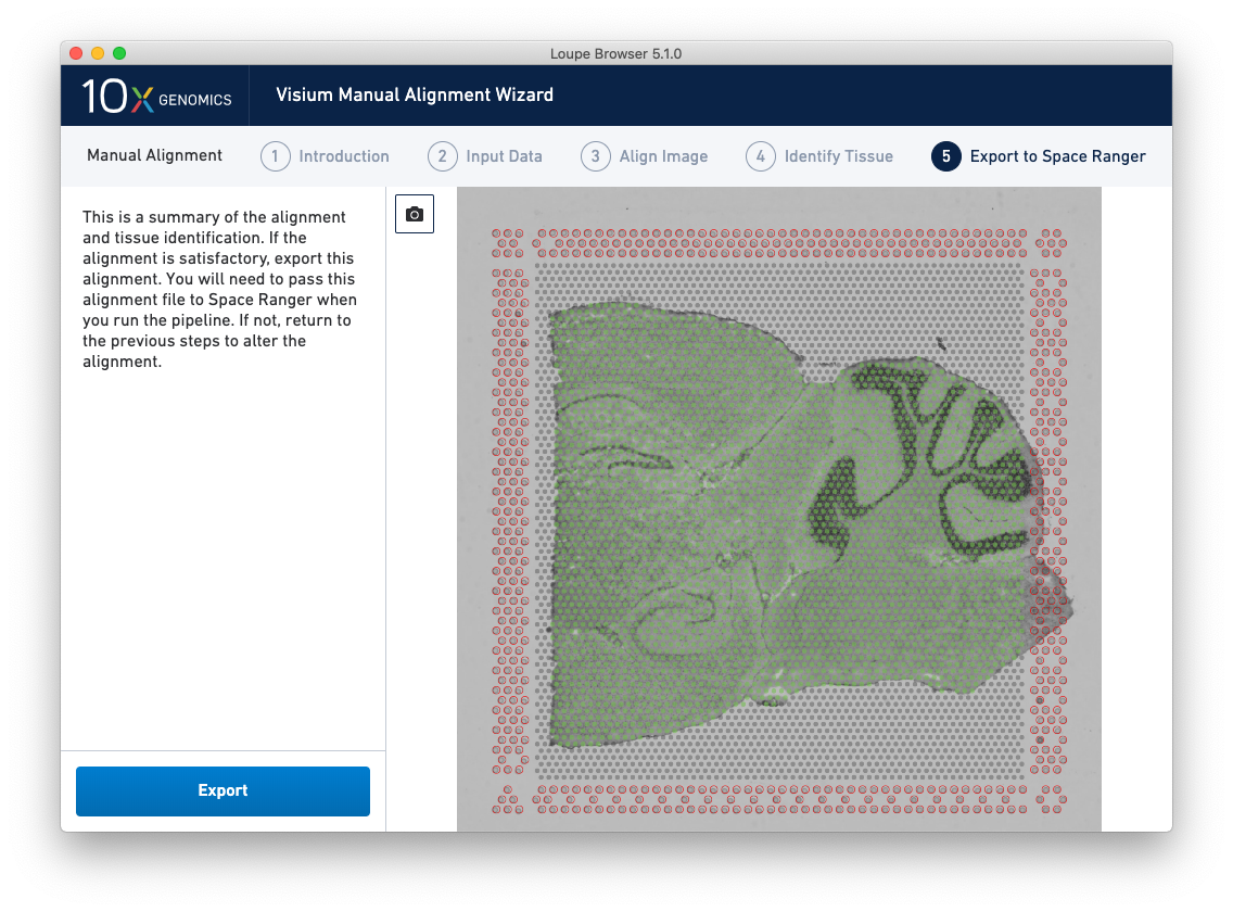
The final step, Export to Space Ranger, shows the complete fiducial spot alignment and tissue selection, as shown below.
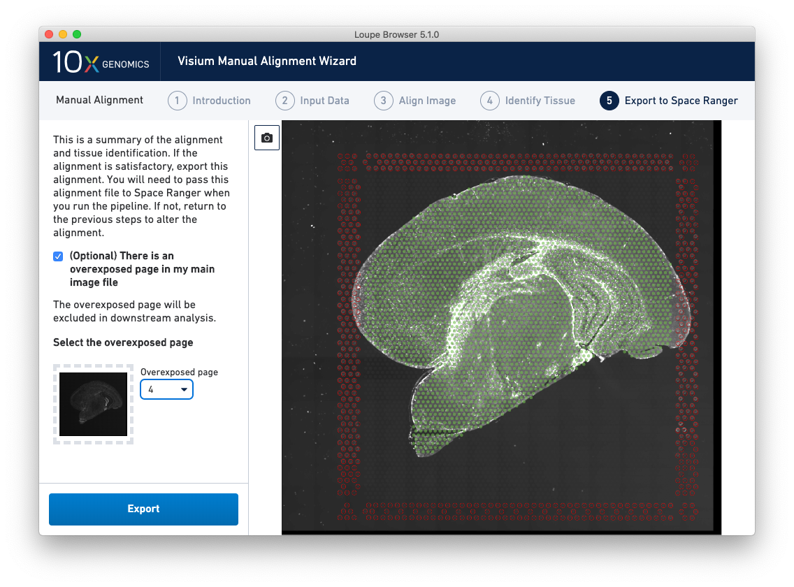
For multi-channel immunofluorescent images where an overexposed capture was added as a channel in the main image file, there is an option to exclude this channel from downstream analysis. This is highly recommended to ensure that the tissue is clearly visible in the web summary and Loupe Browser analysis. An auxiliary image will be excluded by default.
This image roughly mirrors the alignment preview shown in a Space Ranger web summary. Clicking on the camera icon generates a screenshot of the alignment for record-keeping purposes. Click Export to generate a JSON file, which is named after the slide and capture area, if it was supplied in the Input Data step.
This file is used in Space Ranger to override automatic fiducial and tissue detection. The pipeline operator needs to run the pipeline with the loupe-alignment argument, with a path to the generated file. For more information, consult the Manual Alignment instructions in the Space Ranger documentation.
Note: It is important to make the alignment file available to both the computing environment where the pipeline is run, and to the pipeline operator.